Every injection moulded part - from a toothbrush cap to an automotive dashboard panel - must be removed from the mould after solidifying. The mechanism that does this is the ejection system, and at the heart of it are ejector pins. A failed ejector pin causes mould downtime, damaged parts, and in severe cases, a crashed mould. Yet pin specification is frequently treated as an afterthought.
How the Ejection System Works
In a standard two-plate injection mould, the cycle is: clamp → inject → hold → cool → open → eject → close → repeat. The ejection phase proceeds as follows:
- The mould opens - the moving half pulls away from the fixed half. The part remains in the moving half (the core side), held by shrinkage and undercuts.
- The ejector plate (housed within the moving half) is pushed forward by the machine's ejector bar or hydraulic cylinder.
- The ejector pins, mounted through the ejector plate, advance through bores in the mould steel and contact the part.
- The pins push the part off the core, releasing it for robot collection or free-fall.
- The return springs (or machine retraction) pull the ejector plate back, retracting the pins flush with the core surface, ready for the next shot.
Key requirement: Ejector pins must clear the mould parting surface flush when retracted (no protrusion, or the mould won't close), and must apply sufficient ejection force without marking or distorting the part. Both are specification requirements.
Types of Ejector Pins
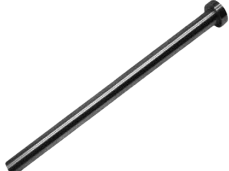
Straight Ejector Pin (DIN 1530 Part A)
The most common type. A uniform-diameter cylinder with a larger-diameter head that seats in a counterbore in the ejector plate. The working section (the section that passes through the mould steel) is ground to h6 tolerance and hardened to minimum 60 HRC.
Available in diameters from Ø1.0 mm to Ø25 mm, with lengths up to 400 mm. The head is typically Ø1.6×d with a 1 mm height for pins up to Ø5 mm, scaling proportionally for larger diameters.
Use when: Ejecting flat areas, ribs, bosses, or any feature accessible with a straight cylindrical pin. This is the default choice for most applications.
Shouldered Ejector Pin (DIN 1530 Part B)
A pin with a reduced-diameter working section - the body is larger diameter (for stiffness and heat dissipation) but steps down to a smaller tip that enters the mould. This allows access to narrow features that a full-diameter pin could not reach, while keeping the overall pin stiff enough to resist bending.
Use when: Ejecting deep, narrow ribs; pins positioned near walls or inserts where only a small diameter can be accommodated at the pin tip; or when a long slender pin would otherwise buckle.
Blade Ejector Pin
A flat, blade-like pin with a rectangular cross-section - essentially a flat key-shaped ejector. Used specifically for ejecting thin ribs that are too narrow for even the smallest round pin.
Use when: Rib width is below ~1.5 mm and a round pin cannot be used; deep, thin-walled features in packaging, automotive trim, and consumer electronics moulds.
Sleeve Ejector (Ejector Tube)
A hollow cylinder that surrounds a core pin. It ejects circular bosses by applying force around the full circumference of the boss base, distributing the ejection force evenly - preventing the distortion that a single off-centre point contact pin would cause on thin-walled bosses.
Use when: Ejecting round bosses, circular posts, or tube-shaped features where a point-contact pin would mark or collapse the feature.
DIN 1530 - The Standard
DIN 1530 is the key standard for injection moulding ejector pins. It specifies:
- Dimensional series - diameter ranges, head dimensions, and length series
- Tolerance on working section - h6 diameter tolerance for sliding fit in H7 bored hole
- Surface hardness - minimum 58–62 HRC on the working section
- Core material - typically H13 hot-work tool steel or high-speed steel (HSS) for demanding applications
- Surface finish - ground finish on working section, Ra ≤ 0.4 µm
- Straightness - 0.05 mm maximum deviation per 100 mm length
IS standard equivalents (Bureau of Indian Standards) align with DIN 1530 for all major dimensions. When ordering from an Indian supplier, specifying "DIN 1530" is universally understood and unambiguous.
Common Failure Modes
| Failure Mode | Root Cause | Prevention |
|---|---|---|
| Pin fracture at head-body radius | Stress concentration + bending from misalignment | Ensure pin bore is perpendicular; use generous head radius; check ejector plate parallelism |
| Pin buckling (long slender pins) | Slenderness ratio too high; unsupported length excessive | Use shouldered pin; add intermediate guide bushings; reduce pin length |
| Galling / seizure in bore | Insufficient clearance, contamination, or thermal expansion binding | Maintain H7/h6 fit; use lubricant; check bore for damage after each tool service |
| Plastic flash around pin | Excessive clearance in bore (worn bore or undersized pin) | Replace worn pins to nominal; re-bore and re-bush worn holes |
| Pin tip mark on part surface | Excessive ejection force; pin diameter too small; pin not flush at retracted position | Increase number of pins to distribute load; check retracted flush position; reduce ejection speed |
| Fatigue cracking | Cyclic compressive and bending loads over millions of cycles | Use H13 or HSS pins for high-cycle moulds; replace pins preventively at defined intervals |
Specifying an Ejector Pin: Checklist
When ordering replacement or new ejector pins, you need to specify:
- Type - straight (DIN 1530A), shouldered (DIN 1530B), blade, or sleeve
- Working section diameter (d) - in mm, h6 tolerance; match to existing bore or design requirement
- Overall length (L) - total pin length from underside of head to tip
- Head diameter and height - typically standard per DIN 1530 for the given pin diameter; confirm if non-standard counterbore exists
- Material - standard carbon/alloy steel for general-purpose; H13 hot-work steel for glass-filled or engineering polymer moulds; HSS for very high hardness requirements
- Surface treatment - untreated (standard); nitrided for improved wear resistance; TiN or TiAlN coating for abrasive materials
- Quantity - always order spares: minimum 10–20% above immediate need for a production mould
Need Ejector Pins for Your Mould?
We supply ejector pins (DIN 1530 Part A & B), die punches, and specialty mould components from Mumbai with same-week dispatch. Straight, shouldered, and blade pins in carbon steel and HSS across a full diameter range.
View Specialty & Mould PartsFrequently Asked Questions
What is an ejector pin in injection moulding?
An ejector pin is a hardened steel pin (DIN 1530) mounted in the ejector plate of an injection mould. After the moulded part solidifies and the mould opens, the ejector plate advances, pushing the pins through bores in the mould steel. The pin tips contact the part and push it off the core, ejecting it from the mould cavity. The pins then retract as the mould closes for the next cycle.
What is the DIN standard for ejector pins?
The primary standard is DIN 1530. Part A covers straight ejector pins (uniform diameter with a head); Part B covers shouldered ejector pins (reduced working section diameter for narrow features). DIN 1530 specifies diameter tolerances (h6 on the working section), head dimensions, surface hardness (minimum 58–62 HRC), material, and surface finish requirements.
Why do ejector pins break?
The most common causes are: bending from misalignment or a bore that is not perpendicular; buckling of long slender pins under compressive ejection load; fatigue cracking at the head-to-body radius from cyclic loading over millions of cycles; and galling in the bore from insufficient clearance or contamination. The head-to-body radius is the most common fracture initiation site - always inspect this area during preventive maintenance.
What tolerance should an ejector pin bore be?
The ejector pin bore in the mould should be reamed to H7 tolerance, matching the standard h6 pin working section (DIN 1530). This gives a sliding clearance fit - the pin moves freely without play but also without binding. Too much clearance allows plastic flash around the pin; too little causes sticking, especially at mould operating temperature. For high-temperature engineering polymers, account for differential thermal expansion in the fit selection.